Documentation - 1:200 ROC Model
Assignment 3 Documentation - 1:200 ROC Model

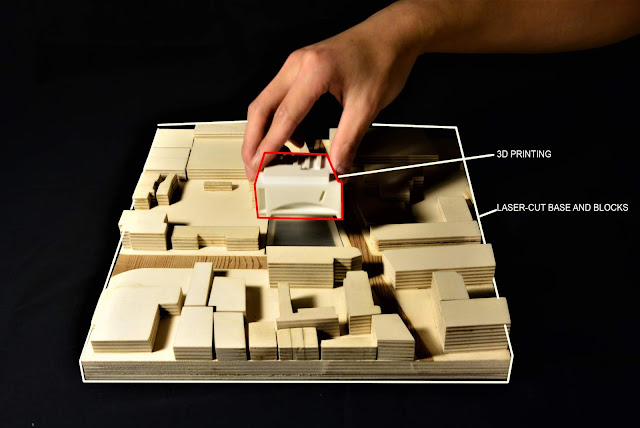
This concept model is challenged to explore exterior form and interior space at the same time. In order to achieve this outcome, I have developed a base with a sliding mechanism, so that the model is able to split in half for interior view show and retract themselves for exterior view.
A wide range of materials and techniques are incorporated, in order to show the contrast of the surrounding road and building blocks. Externally, the used of laser-cut on veneer and plywood demonstrates the concept of bridge brick arch with details. Internally, the red acrylic blocks brutally illustrated the concept of structural loading and its vertical element within the building. A few details on the skylight of the building, curved wall of the facade and acrylic finish for the sliding base were worthwhile exploring, which elevated its quality and the level of detail. Lastly, in terms of the accuracy of the model, it is ensured by the use of laser cutting and digital file preparation as a reliable source of information.
Scale: 1:200
Material & Techniques:
Laser-cut - Cut and Engrave for facade timber veneer facade
Laser-cut - Plywood building facade and structural floor
Laser-cut - Red acrylic block for vertical design elements
Laser-cut - Base protection for sliding mechanism.
Timber work - Base with a sliding mechanism.
Base construction:
1. Preparation(3 hrs,$0)
The preparation for this project, I used SketchUp to digitalize the sequence of the process before I started my base. This demonstrates the construction sequence for the sliding base as below. The whole exercise of preparation makes the process clear in my head.
Please see model instruction below:
 Step 1: Using the router to recess the timber for the drawer slider to sit in. Additionally, laser-cut the profile of the timber base and also cut holes for screws and magnetics to secure. Then installing a 6mm acrylic protection layer on top of the timber surface with two pieces of magnets. The idea of the magnetics allows the sliding timber board to find its assembly point more easily.


2. Construction
1. I picked up a Claymark 285 x 19mm x 1.2m Premium Grade Dressed Pine Sheet from Bunning, which suits my purpose and size.
Then, the construction begins with routering the base for the slider. First of all, I drew all the critical dimension on the timber that I am going to work with. The dimension of the recessed area depends on the lengths and thickness of the slider.(1 hrs,$25 on timber)
3. Laser cutting for base
After measuring the timber base, then I model in cad and transfer to laser-cut machine. With the installation of 6mm acrylic layer, it will protect the solid timber surface from scratching during moving.(2 hrs,$15 on Arcylic, &15 on laser-cut service,$9 on slider)
4. Magnet
With the installation of the magnets, I lined up the base with movement part to ensure the alignment of the magnet. Then, I used the drill press for the recess, which is 9mm into the timber. The drill press can be set up to reach 9mm exactly where I wanted to. (0.5 hrs,$2 on magnets)


3D Sketchup model
 Step 1: Using the router to recess the timber for the drawer slider to sit in. Additionally, laser-cut the profile of the timber base and also cut holes for screws and magnetics to secure. Then installing a 6mm acrylic protection layer on top of the timber surface with two pieces of magnets. The idea of the magnetics allows the sliding timber board to find its assembly point more easily.
Step 2: Secure the drawer slider into the moving timber board. Additionally, install the magnetics into the centre of the timber.

Step 3: Install the base model with the moving components into the recessed bay.
Step 4: Testing

Operation stage 1 - Open

Operation stage 2 - Open

Operation stage 3 - Enclosed
1. I picked up a Claymark 285 x 19mm x 1.2m Premium Grade Dressed Pine Sheet from Bunning, which suits my purpose and size.
Then, the construction begins with routering the base for the slider. First of all, I drew all the critical dimension on the timber that I am going to work with. The dimension of the recessed area depends on the lengths and thickness of the slider.(1 hrs,$25 on timber)
 |
| Plan on timber |
2. Router
I used the router to trim of 10mm of the timber for the tracking system. The idea of recessing the base is to make the slider go flush with the surface. Then I was going to chisel out the round edge, but it did not affect the slider to operate. Therefore, I finished this process by sanding the surface. (4 hrs,$0)
 |
| Setting the guide timber on the right, 39mm offset from the line, then use the router to recess 10mm into the base. |
 |
| Finish routering and sanding the surface with 380 grit sandpaper |
 |
| Testing the slider in recessed bay |
After measuring the timber base, then I model in cad and transfer to laser-cut machine. With the installation of 6mm acrylic layer, it will protect the solid timber surface from scratching during moving.(2 hrs,$15 on Arcylic, &15 on laser-cut service,$9 on slider)
 |
| Laser-cut the profile of the timber base
Then. I Installed the base with Zenith 5G x 15mm Zinc Plated Hinge-Long Threads Countersunk Head Timber Screws. With the flat top, it can be screwed down and go flush with the acrylic surface.
 |
 |
4. Magnet
With the installation of the magnets, I lined up the base with movement part to ensure the alignment of the magnet. Then, I used the drill press for the recess, which is 9mm into the timber. The drill press can be set up to reach 9mm exactly where I wanted to. (0.5 hrs,$2 on magnets)


 |
| Drill press into the timber 9mm deep for magnet |
5. Assembly(0.5 hrs,$5 on screws)
Finally, install the base with the moving part and test the sliding and the magnet system for any final adjustments.
Finally, install the base with the moving part and test the sliding and the magnet system for any final adjustments.

Building model construction:
1. Preparation(5 hr, $0)
The preparation for the building was that I Rhino to model the Rail operation building in 1:200 scale and I was able to export into the laser-cut template. The construction will be the two main part.
First of all, is the timber veneer facade on 1.5mm acrylic. Secondly, the building will be constructed by plywood and the interior space will be the laser cutting the red acrylic for expression.

First of all, is the timber veneer facade on 1.5mm acrylic. Secondly, the building will be constructed by plywood and the interior space will be the laser cutting the red acrylic for expression.

1. Construction
1. Laser cutting and bending acrylics
Laser cutting the acrylic and bend with spot heater. Video below shows how I bend it use a test piece and follow by the model piece. (1 hrs,$15 laser-cut service)
Laser cutting the acrylic and bend with spot heater. Video below shows how I bend it use a test piece and follow by the model piece. (1 hrs,$15 laser-cut service)
 |
| Tips: prepare some acrylic to guide the angle of bending |
 |
| Tips: always use a test piece first! |
As you can see in the video, there is a critical moment when the acrylic starts to bend due to the high temperature. Once it starts to bend, the material should be quickly picked up and bend it into the right angle by using the profile provided. Finally, the material is held in place for 5 mins, in order to cool down the material.
Apply veneer on the facade(0.5 hrs,$15 laser-cut service, $10 timber veneer and uhu glue)
 |
| Apply veneer on the facade after laser cutting. (laser cut file attached appendix) |
 |
| Exterior facade completion |
3. Interior space
Construction of interior space with red acrylic blocks. Laser-cut the acrylic then glue them into one piece.(3 hrs,$15 laser-cut service, $30 red acrylic board)
 |
| Laser-cut red acrylic then glue them together |
 |
| Tips: Using clamps to secure the block |
 |
| Sending the floor plate after laser-cut, in order to remove the burn marks on the edge |
Assembly Timelapse viedo
 |
| Assembly of the floor plate with column and red acrylic blocks |
 |
| Assembly of the floor plate with the exterior facade |
 |
| Assembly of the floor plate with the exterior facade |
3. Assembly
Testing on the sliding base for final adjustment. Then, the whole model is glued down into the sliding components.

Comments
Post a Comment